
|
E-M1 Mk.II High-Res Mode Does it Work and How? |
|
| My other articles related to the Olympus OM-D System. |
|
See also a sequel: E-M1 Mk.II High-Res Mode, Part 2 |
|
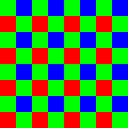
Sensor Shift as a Way to Increase Resolution The sensor-shift technique has been used for a few years already in some applications of medium-fornat photography, at the expense of some complication and a serious extra cost. Olympus was the first manufacturer who introduced it into a product normal people, like you and me, can afford and use. This was the E-M5 Mk.II in 2015. Just months later Pentax offered a similar feature, called Pixel Shift Resolution in their K-3 II model. We will come back to that later. The method uses a typical image sensor, but does it in an innovative way. To understand it, we must start from how such a sensor usually works. Pixels, Photosites, and the Bayer Matrix The most common arrangement is the-so-called Bayer matrix: an array of photosites (light receptors), arranged in a rectangular grid, with each photosite responding to, roughly speaking, one component (or spectral region) of light: Red, Green, or Blue. |
|
In the Bayer matrix, the photosites are arranged into a repetitive pattern of 2×2 squares. Each includes one photosite for Red, one for Blue, and two for Green component. Having two Greens for each Red or Blue makes it easier to arrange photosites into a repetitive pattern. There is also a nice excuse to do it this way: our eye is more sensitive to Green, so it carries more luminance (brightness) information that either of the other two. How convenient.
|
|
|
Photosites are often confused with (and referred to as) pixels. This is wrong and misleading, often resulting in false conclusions. The principal distinction is that while photosites are physical entities, really existing on the sensor surface, pixels are purely abstract constructs, stored in memory, and arranged in a rectangular grid. A photosite responds to received light (one RGB component) at its physical location by generating a signal, translated into a numeric value. A pixel stores three such values as RGB components, describing brightness and color of light at its assigned logical location. This means that three photosites capture the information equivalent to that contained in one RGB pixel. How many photosites are actually used for that and how, depends on the associated software. Usually the image created by the camera has a number of pixels equal to the that of photosites, and that's the number listed in the specs. In this arrangement, the abstract grid of pixels is mapped into the physical grid of photosites: every pixel has an associated photosite. During the so-called demosaicing (a part of raw-to-RGB conversion) that's the photosite supplying its color component's value to the pixel, and whose neighbors are used for interpolation of two other components. Yes, that's right: for each pixel only one component is known from its associated photosite; two others are computed by interpolation from its nearest (two or four) neighbors responsive to the missing color.
This, actually, is nothing else but upsampling. Your 24 MP image is really an 8 MP image upsampled to This, however, does not have to be the case. This method uses multiple exposures, each followed by information readout, to generate a single image. Here is how it works. The first exposure is done with the sensor it its original position. When the camera reads the signal from the photosites, we store for each pixel just one of its RGB components, the one from the photosite assigned to that pixel. Next, the whole sensor is moved by one photosite grid step in one of the four principal directions. At each original grid node location there is now another photosite, sensitive to another color component. Another exposure is made; the camera does the readout again and sends this signal not to each site's associated pixel, but to that bound to the original one (before moving the sensor). Now every pixel will now have two readouts, of different RGB components, measured at the same physical spot! Repeating this step twice more in a square pattern, we end up with every pixel receiving four RGB values, recorded by each member of the 2×2 photosite team at the time when that member was at that pixel's location (more exactly: at the original location of the photosite associated with that pixel). The only problem is that each of the four readings was done at a slightly different time. Having all RGB components as they were read at the right location makes the demosaicing interpolation no longer needed. Just store them in the pixel (averaging the two Greens, one too many). |

|
This little square dance alone should bring, in theory at least, significant advantages to the image quality. The total amount of information is quadrupled, with each pixel using the actual readings for all color components from the right physical location. Quadrupling the light reaching the sensor (four exposures) should also cut the random noise in half. Last but not least, false-color artifacts often arising in the demosaicing process are no longer a problem. What was described above is exactly what Pentax does in their Pixel Shift mode. The difference is that while Pentax exits the process at this moment (cashing in the winnings: better pixels), Olympus continues to the next stage. |
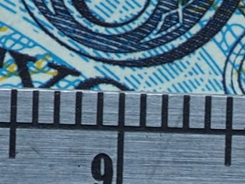
| Standard resolution | High resolution mode | |
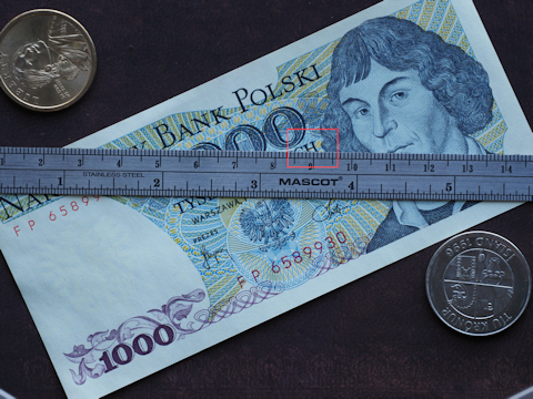
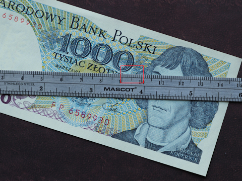
[1.1] |
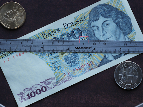
[1H.1] | |
|
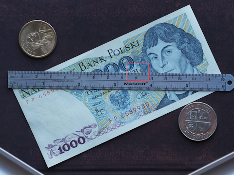
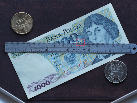
Full frames, reduced in size, with sample origins shown.
Aperture priority (+.3 EV): 1/15 s at F/8, ISO 200 | ||
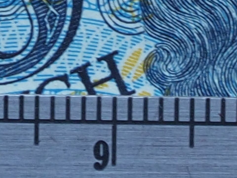
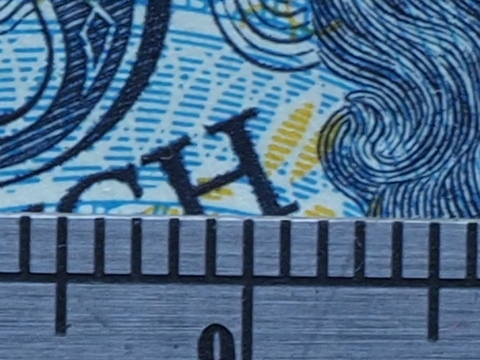
[1.2] 1:1 sample from the original |
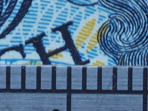
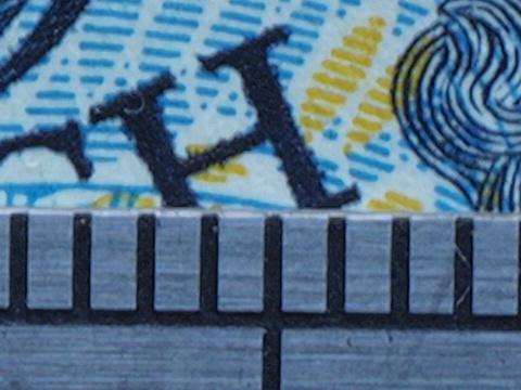
[1H.2] 1:1 sample from the original | |
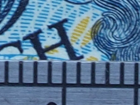
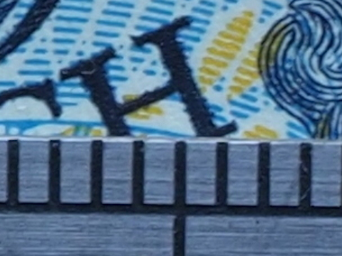
[1.3] As above, upsampled to match the HR size |
[1H.2] (yes, not a typo!) Same as above | |
|
This is quite interesting. Comparing unaltered 1:1 fragments, we see that the native-resolution [1.2] seems a bit less fuzzy than the high-res version [1H.2]. On the other hand, the latter shows more detail; for example, look closely at the edge of letter 'H', or its ink texture. What does that mean is that HR provides some increase in resolution, but it is smaller than the increase allowed by the new pixel density. Upsampling of [1.2] into [1.3] to compare it, again, with [1H.2], confirms this observation. Image becomes more fuzzy (as it should), and while contours seem quite sharp, there is no contest about detail, see the letter 'H' again. Conclusion: Sample Set #1 shows that the HR Mode provides more sharpness and detail than the native resolution; the gain is, however, not as high as the new pixel resolution would allow, most probably limited by lens quality. Here I used the same subject, but shot it with the MZD 12-100/4.0 ED IS PRO lens at 100 mm, F/8. While this is a zoom, it has very good press (I like it, too) and I was hoping it will be able to make a better use of the HR Mode. This set does not bring in anything new compared to Sample Set #1. The lens seems to out-resolve the ZD 50/2.0 Macro at normal shooting distances, while at closer ones the situation seems to be reversed (see below). |
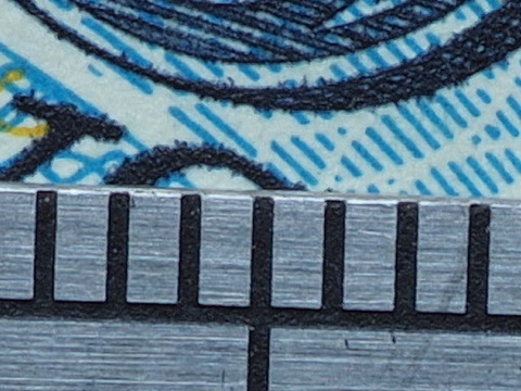
| Standard resolution | High resolution mode | |
[2.1] Full frame reduced in size |
[2H.1] Full frame reduced in size | |
[2.2] 1:1 sample from the original |
[2H.2] 1:1 sample from the original | |
[2.3] As above, upsampled to match the HR size |
[2H.2] (yes!) Same as above |
|
The bottom line is the same: the HR Mode resolution is improved, but less than expected. Is this the lens again, or maybe some other reason? This calls for drastic measures, I thought, and brought in my secret weapon, the sharpest lens I have: the ZD 50/2.0 ED Macro. True, I have to use it with a FT->μFT adapter, and AF is not as responsive as that with native μFT lenses (even on E-M1 bodies), but this is, I hoped, like U.S. cavalry showing up in a Western movie. No more talk, just samples. |
| Standard resolution | High resolution mode | |
[3.1] |

[3H.1] | |
|
Full frames, reduced in size, with sample origins shown.
Aperture priority (0 EV): 1/15 s at F/8, ISO 200 | ||
[3.2] 1:1 sample from the original |
[3H.2] 1:1 sample from the original | |
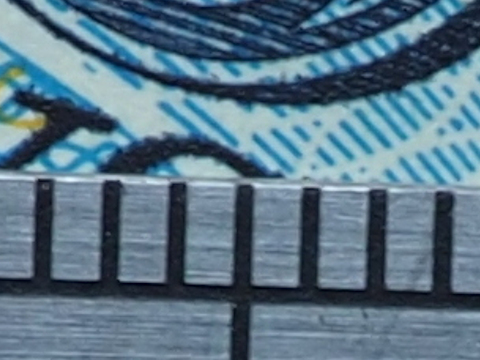
[3.3] As above, upsampled to match the HR size |
[3H.2] Same as above | |
|
One look at the second row and we need nothing more: even in 1:1 pixel view sample [3H.2] is as sharp as [3.2], in spite of the magnification being 1.6× higher. I was hoping this lens will bring some improvement — but not this much! We don't even need to look at the third row; it just confirms the first impression. Conclusions:
Now, look at this. This lens was introduced on the market in 2003, together with the very first Four Thirds camera, the Now, that we are done with resolution, let's have a look at another area where the HR Mode may offer something: the noise. We discussed this in the first part of the article, so what remains is just to see the image samples. Here I decided to go for the pencil box scene, with smooth, out-of-focus gradient transitions being the favorite playground for noise demons. As opposed to my previous arrangements of the same subject, this time I used diffused daylight, with an old computer game box used as defocused background. The presentation is identical as for the resolution sample series, so no additional explanations are necessary. |
| Standard resolution | High resolution mode | |

[4.1] |

[4H.1] | |
|
Full frames, blah, blah, blah
Aperture priority (-1.3 EV): 1/60 and 1/50 s at F/4, ISO 1600 | ||
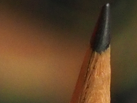
[4.2] 1:1 sample from the original |
[4H.2] 1:1 sample from the original | |
[4.3] As above, upsampled to match the HR size |
[4H.2] Same as above | |
|
The unaltered 1:1 fragments [4.2] and [4H.2] look, to a naked eye at least, quite similar. (Inspecting whole frames shows that the HR image does have some advantage here, but nothing dramatic.) This means they do not differ much in terms of noise per pixel. This is both good news and bad news.
Upsampling [4.2] to [4.3] and comparing that to [4H.2] levels the field making both samples equally magnified. Clearly, the HR version is cleaner. (It is sharper, too, as discussed in Sample Set #1, using the same lens.) Conclusions:
What Difference Does All This Make? As a concept and a piece of technology, the approach used by Olympus is brilliant; I also find it aesthetically pleasing, just beautiful. It also works, which means the engineers were able to take care of dozens (maybe more) of pesky ifs and buts in the implementation; these often ruin great concepts in practical use. While it can (and should) be enjoyed as a piece of engineering art, its practical significance for 99% of photographers (and I mean advanced amateurs and professionals here) is negligible. First of all, we already have more pixel resolution than we need or actually can use for most applications. Sadly, the general public does not (and never will) understand that once you reach some level, any further increase in pixel count is just a waste of resources and/or a marketing gimmick. They are not aware that an 8 MP camera with a good lens makes better images than a 30 MP one with a crappy piece of optics. Educating the market would be counterproductive for manufacturers: it is much cheaper to make a sensor chip delivering more pixels than a lens with higher optical resolution. Therefore, the higher resolution will be really useful in some special applications only — when and if it works within a given context. Secondly, at the current stage the sensor-shift HR technique suffers from some limitations. Two of those stand out.
But even if all this will not affect the mentioned 99% of us, for some dedicated enthusiasts (like me and, probably, you), it is a fascinating development, opening new possibilities of learning and experimentation. See also: More on the E-M1 Mk.II High Res Mode, a sequel to this article. References
|
|
| My other articles related to the Olympus OM-D System. |
| This page is not sponsored or endorsed by Olympus (or anyone else) and presents solely the views of the author. |
| Home: wrotniak.net | Search this site | Change font size |
| Posted 2017/03/27, last updated 2019/04/18 | Copyright © 2017-2019 by J. Andrzej Wrotniak |